Need some basic circuit help

Stein

Stein
If anybody happens to be accustomed to single-layer PCBs, let me know.

there's no way I'm getting to the back of this PCB to re-solder that capacitor. All of the important amplifier things (transistors...?) are glued/taped down to the casing with thermal tape.

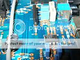
There are, however, copper rings around all of the holes in the PCB for the component-leads. Do you think that these copper bits are linked to the solder joint on the other side, or just a remnant of cutting the holes?

Here are the rings I'm talking about:

And just in case here's the capacitor that was half detached. I put the broken lead into its hole and taped down the capacitor, but I have no idea if the lead is making contact or if the duct tape is safe.
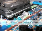


I'm assuming the duct-tape glue is non-conductive, but you know what they say about assuming...

All help appreciated. I want to get this thing in my car and hooked up already.


2point5RS_Dan

HATER DAN
Post bigger pictures and I can get you going in the right direction.

Photobucket seems to downsize everything as of late.

You'll want to use solder to reattach anything rather then ductape.


Chris

YARRR SUBY MONSTER!!
Sometimes they go through. sometimes they don't. In the case of that picture, they don't go through. I can see the PCB fiberglass material inside the holes, also, if they go through, the solder wicks through the whole so it's obvious. You'll have to solder it on from the side it was originally soldered to for it to be reliable/work at all.

Duct tape = bad. I have no idea what you're trying to tape there, but if you need to tape anything electrical they make this wonderful product called electrical tape. Buy some. If there's an option for cheap or expensive, get the expensive roll. It's thicker, sticks better, doesn't dry out as bad, stretchier, and works better.

 
Last edited by a moderator:

Stein

Stein
The duct tape is just to hold the capacitor to the PCB so it doesn't wiggle around while driving. Nothing electrical is going on with the tape.

I think that gaining access to the rear of the board is going to be a big project in and of itself. There's a bunch of three-pronged components (no idea what they are) that are secured down to the casing with adhesive thermal pads. I don't know if un-sticking them all will leave the pads reusable or not, but they're really stuck down hard.

 
Last edited by a moderator:

Chris

YARRR SUBY MONSTER!!
The duct tape is just to hold the capacitor to the PCB so it doesn't wiggle around while driving. Nothing electrical is going on with the tape.

I think that gaining access to the rear of the board is going to be a big project in and of itself. There's a bunch of three-pronged components (no idea what they are) that are secured down to the casing with adhesive thermal pads. I don't know if un-sticking them all will leave the pads reusable or not, but they're really stuck down hard.
Duct tape leaves really sticky nasty residue. It will attract dust and be electrically conductive.

You can argue with everything I say, or learn from my experience.

Those three-prong things you speak of are the power transistors, basically what makes the amplifier part of the amp.

Also, it WILL jiggle loose. No matter how much tape you use. It might last for a month, or two, but ultimately it's going to be an issue. You'll be on a date and your amp will suddenly start making squeaking squawking noises.

When I have to fix stuff like this, and it's way to much of a pain to take it apart to get access. I make access. Think cutoff wheel and cut a hole in the back of the casing, then glue it back together....


Stein

Stein
Cutting my way in... That's brilliant!

I wasn't arguing with you, just trying to clarify what I was trying to do with the tape.

 
Last edited by a moderator:

Boz

New member
Those components on the PCB are through hole not SMT (Surface mount) so the traces are attached to either the upper or lower solder pads/lands.

If you still need help with this I can do it.


Stein

Stein
Thanks, but I got this figured out a while ago.

It took a pair of Dremel brushes and a few hours of cutting to get in the back, but I made it. Then I just fed wire through and soldered to the back.


Latest posts

Back
Top