Chris
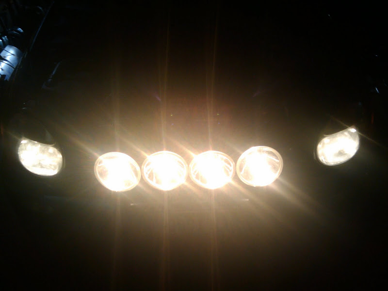
YARRR SUBY MONSTER!!
If you're one of those people who hear the word “Relay” and get scared... This guide is for you.
Also, I focus on wiring hellas, so read on if that's what you want.
So what the heck IS a relay?
Why would I ever use a relay?
How do I use a relay?
It's pretty simple, folks. A relay is a switch. I'm going to assume here you know how to hook something up to a battery with a switch. That's fairly straight forward, right?
Well, a relay is pretty much just as simple.
A relay is a switch that, instead of being turned on and off by user input (ie. Your finger), it's turned on and off by an electrical signal.
There are a few reasons you would use a relay, but the general idea boils down to this. You want to turn something on and off with a signal load that can't support the full current of what you want to run. WHAT THE HECK DOES THAT MEAN?!
It means this. Say I want to add 4 Hella 500's to my car. I want them to come on when I turn on my high beams. But here's the problem, I can't just wire them into the car wiring harness to my high beam light bulb. It's only designed to handle the pathetic whimpy high beam. So adding ~14 amps to that circuit will hopefully just blow the fuse. I say hopefully blow the fuse because the alternate is it'll melt your wiring and start a fire.
You could run a wire into your cabin to turn the hellas on and off with battery power, but that's annoying. Now you have to turn off your high beams AND hellas for traffic.
SO here is where you meet Mr. Relay. Remember, he's a switch. So you have power directly from your battery to the hellas using the relay as a switch to turn them on and off.
That's great, how does the switch know to turn on and off?
It uses the power to high beams as a SIGNAL to turn the relay switch on, or off. So no power (ok, like 1/4 of an amp) is drawn from the car wiring. Pretty nifty, eh?
Ok dood, that's confusing, give me some pictures!!!
I've disected a relay for you.
Here's a relay in the off state.
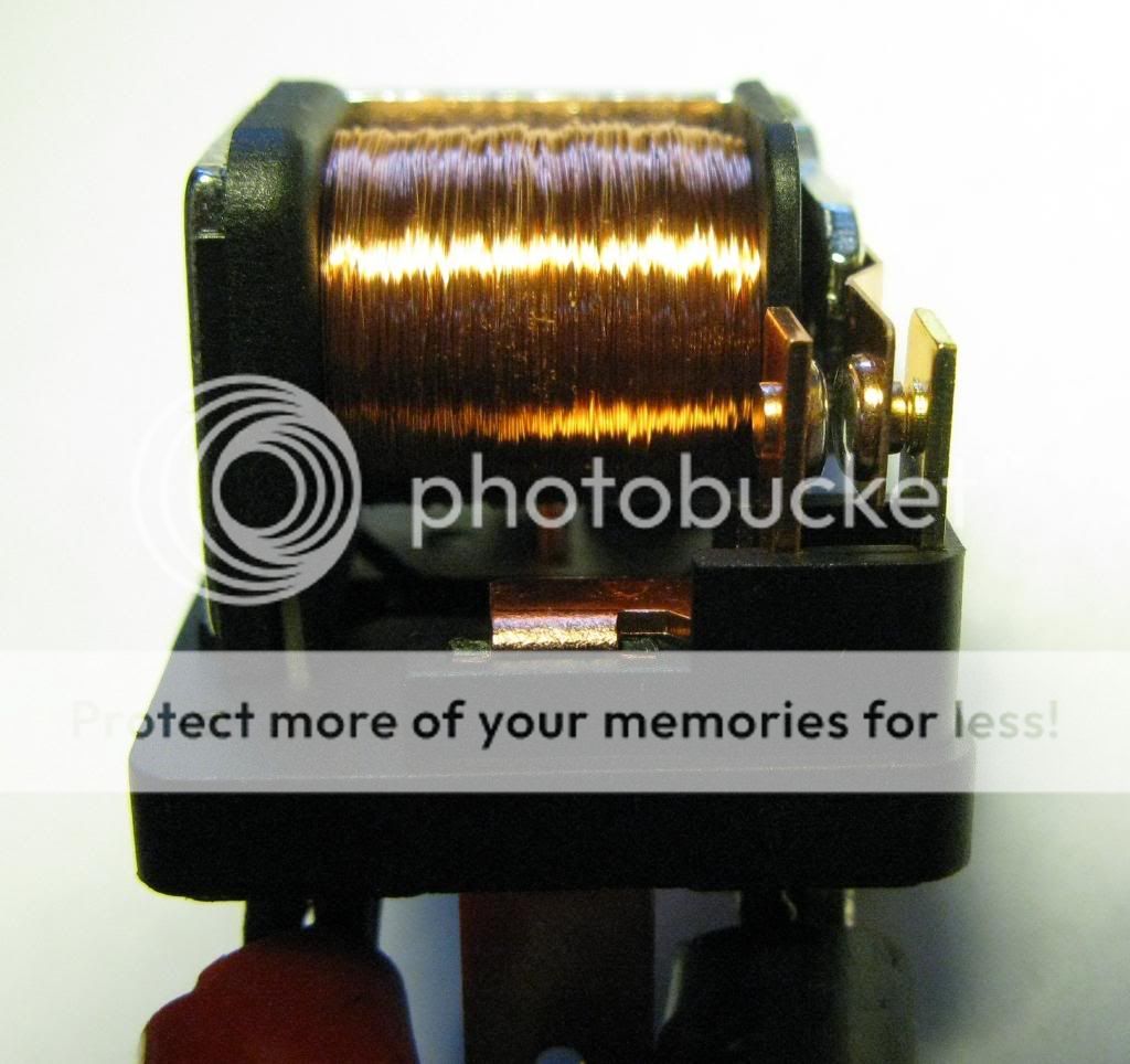
Note a few things, the coil. That is what the signal goes to. The coil is an electro-magnet. When it gets power it physically moves the contacts. The things you can see at the front of the realy.
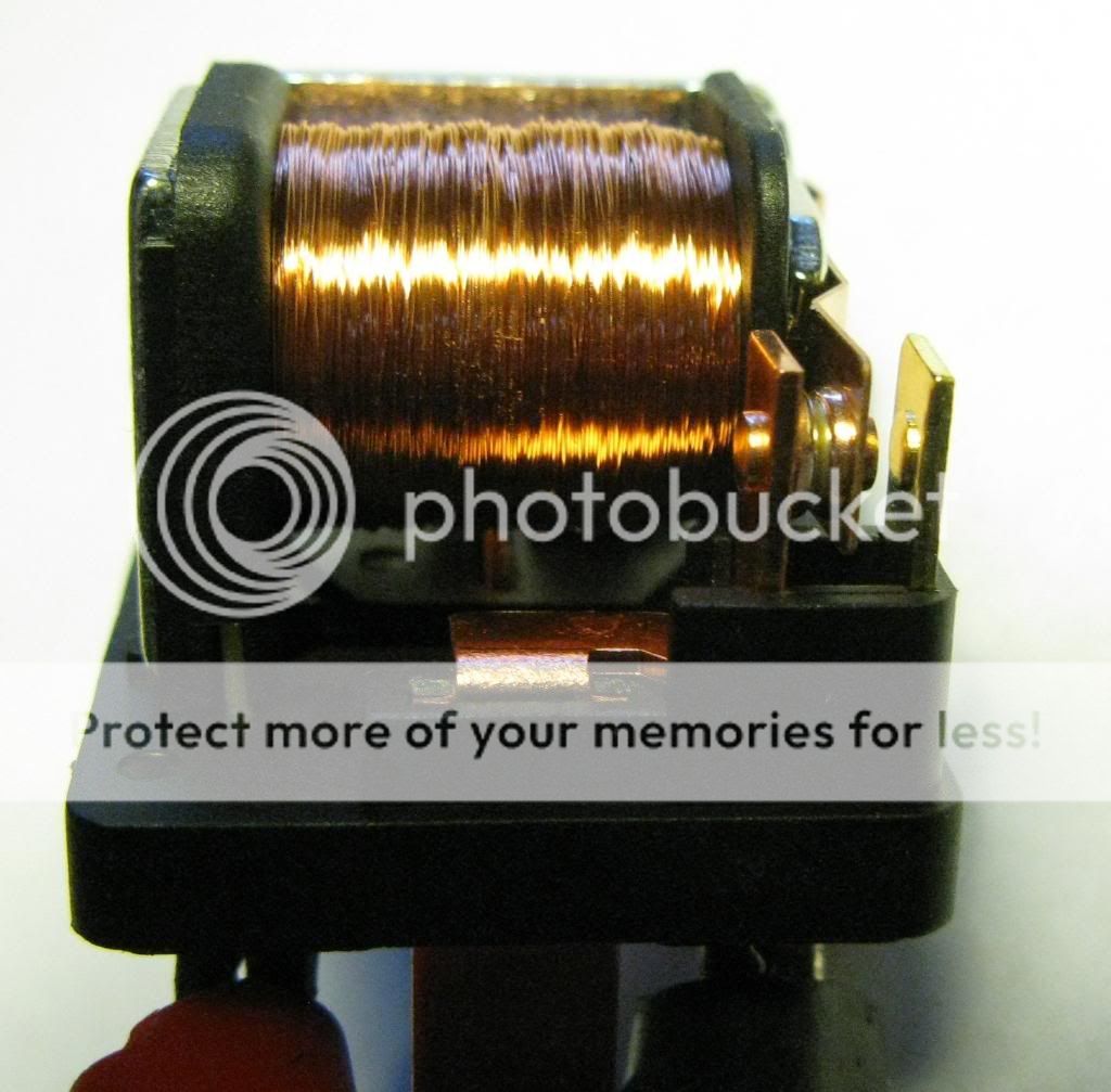
When you give it power the contacts move and connect the circuit.
This is what it looks like on
This is the case of the relay, it has the wiring diagram. The numbers correspond to numbers by the terminals on the bottom. More to follow.
Here's the case.
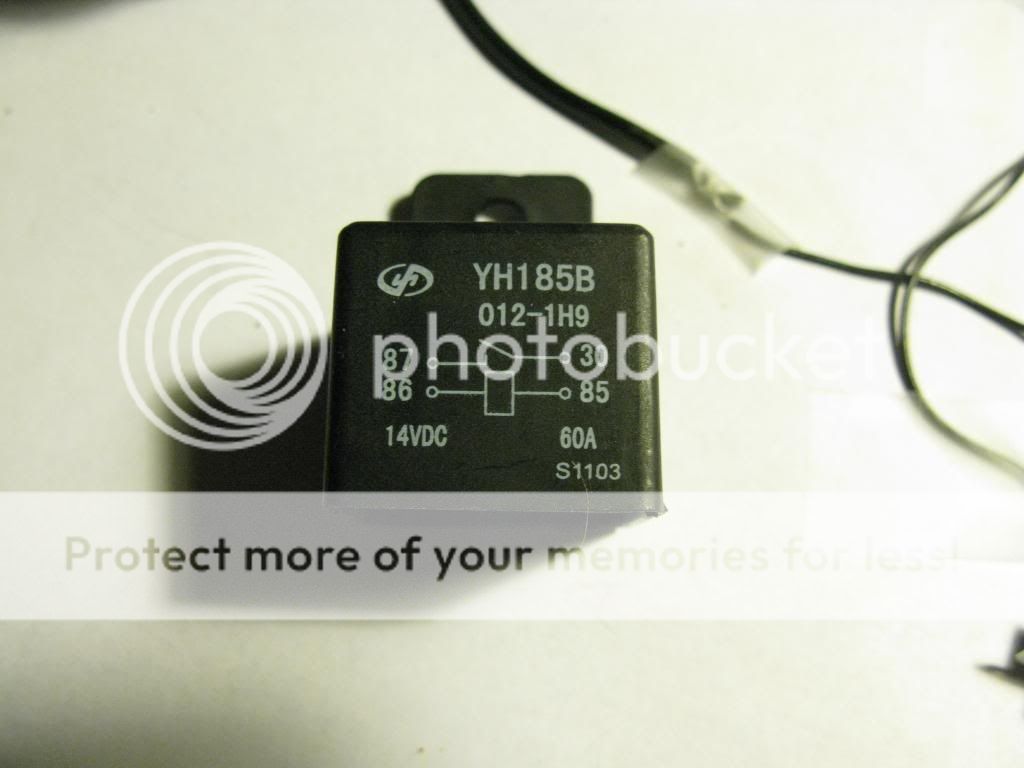
From this picture, it's easy to figure out how it works.
87 and 30 are the switch terminals. The load terminals, the one the power wire from the battery to the hellas goes through. Think of this half just like a normal person-operated switch.
85 and 86 are the coil. When you give the coil power it's like taking your fat finger and pushing a physical switch. It connects pins 87 and 30 together to make the circuit to turn on your lights.
I should note here, polarity doesn't matter. So you can hook up the coil either way, and have power going through the switch either way.
Here's the bottom of the relay, the part you hook stuff to.
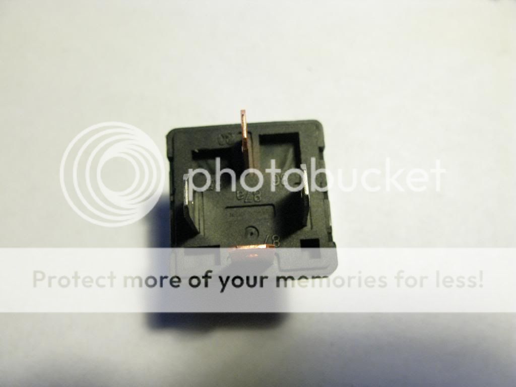
You can see it has the same number that were on the cover.
Note: the switch contacts are copper colour. The signal contacts are silver colour. Almost all the relays I've seen are like this, so that's a big help.
Ok, so I understand what a relay is, tell me how to hook wires up to it!!!!
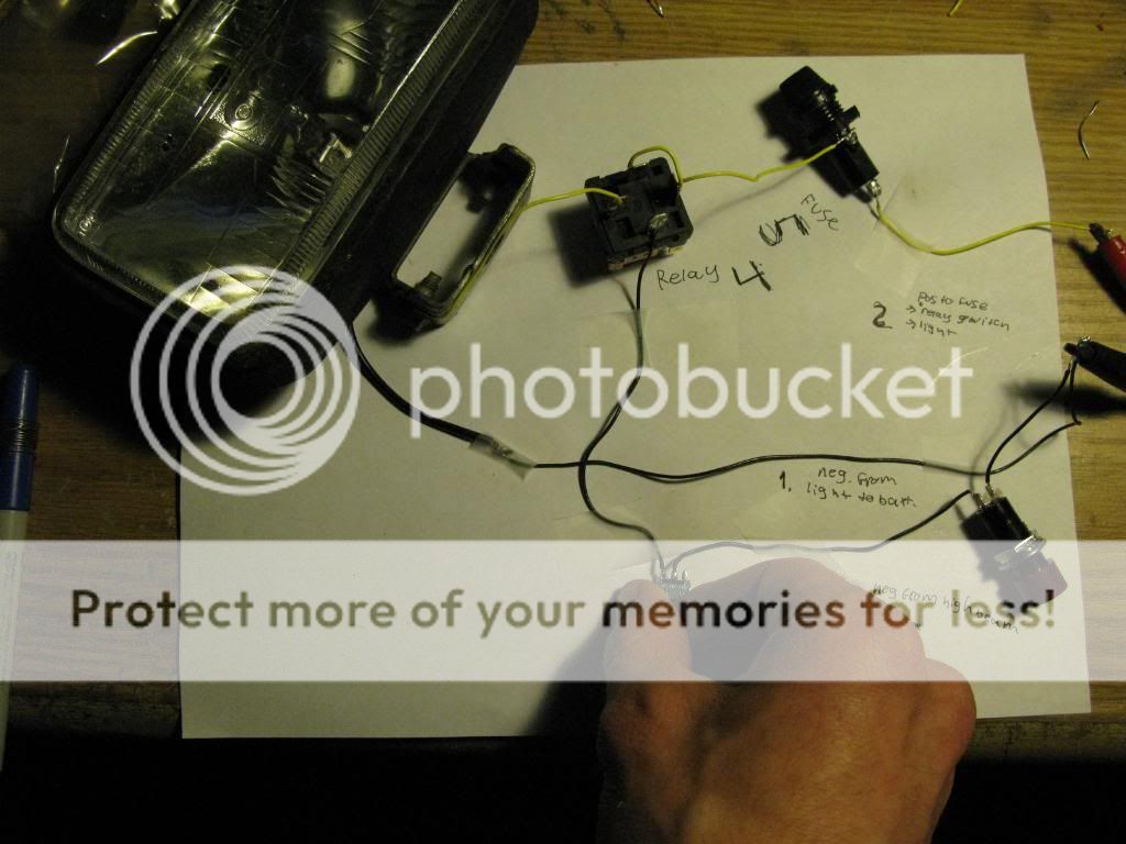
I've made a mock up of how your car is wired on my desk. So here we go.
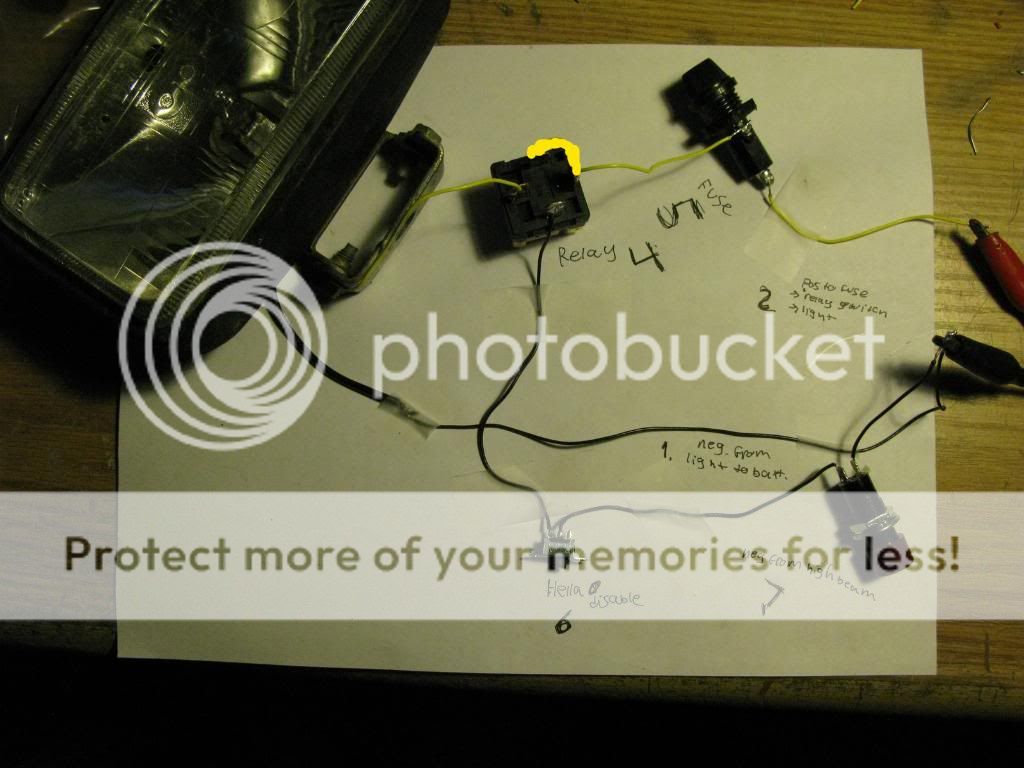
In case you can't read my crappy hand writing, this is what the numbers are.
Also, you'll see I've scribbled some yellow with paint to emphasis there's a yellow wire there. It's hard to see in the pic.
So what do we have here?
Power will flow from the battery to a fuse. That's pretty straight forward. The fuse is protecting both the relay/light circuit, AND the signal wire circuit.
The power goes from the fuse to the switch half of the relay, then to the light. (not a hella in this case, but still 55w)
There's a negative from the light to the battery
So far, this is straight forward.
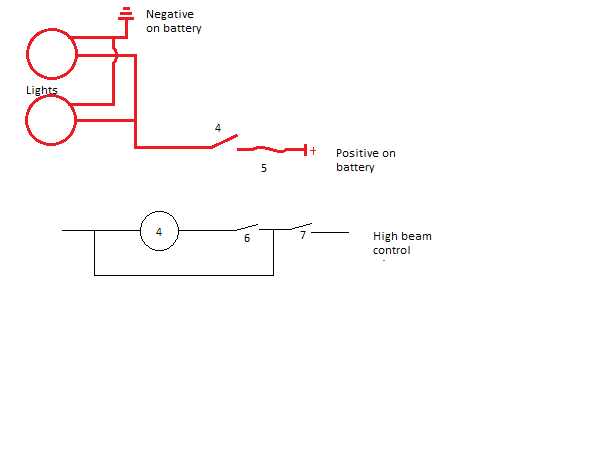
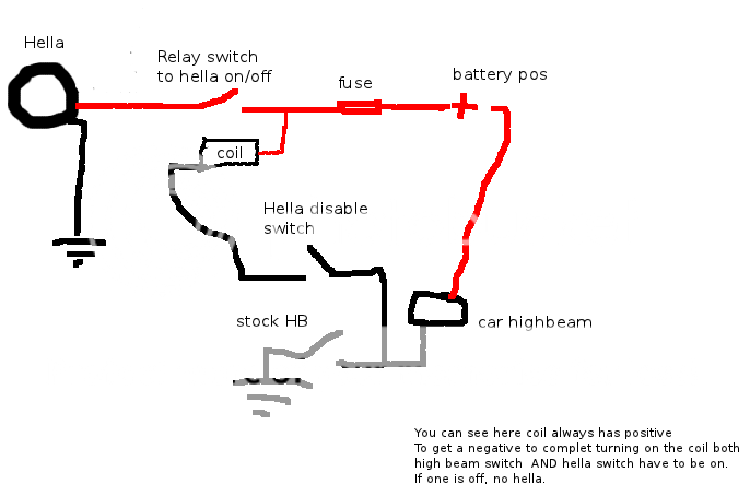
Then my scribbly yellow to half of the coil. We need positive and negative to power the coil, negative comes from the high beam, so I gave it positive downstream of the fuse. So now the coil has a fused positive. Makes it for a safe installation.
Then the negative to turn on the coil from your high beam. Explained below.
Finally the red button simulates the high beam toggle inside your car, the little tiny switch is the hella disable.
Basically allows you to turn on the high beams but have the hellas off (useful for inspection, etc).
So now you can see, if the high beam button is pushed AND the little switch is on, negative will be delivered to the coil. It'll turn on, close the switch, and turn on the light.
--------------------
Negatively switch headlights.
I'll take an aside here to explain. Headlights on a subaru are negatively switched. Meaning this. The bulb has two filaments, one for high, one for low. That's why there's 3 pins. The common always gets positive, and negative is SWITCHED to either the low beam, or the high beam pin. Hence, negatively switched. This is why we use the negative from the high beam to activate the relay.
If you have a newer car with a high and low bulb separate, the concept is the same. Your projector/low beam is always on, your high beam gets a negative connected when it comes on
---------------------------
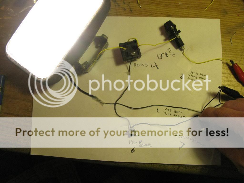
So let's press my buttons.
Currently the hella disable is OFF. We shall press the High beam button, what happens?
NOTHING! Good, that's what's supposed to happen. In the car, the high beam would have come on, the hellas would have stayed off.
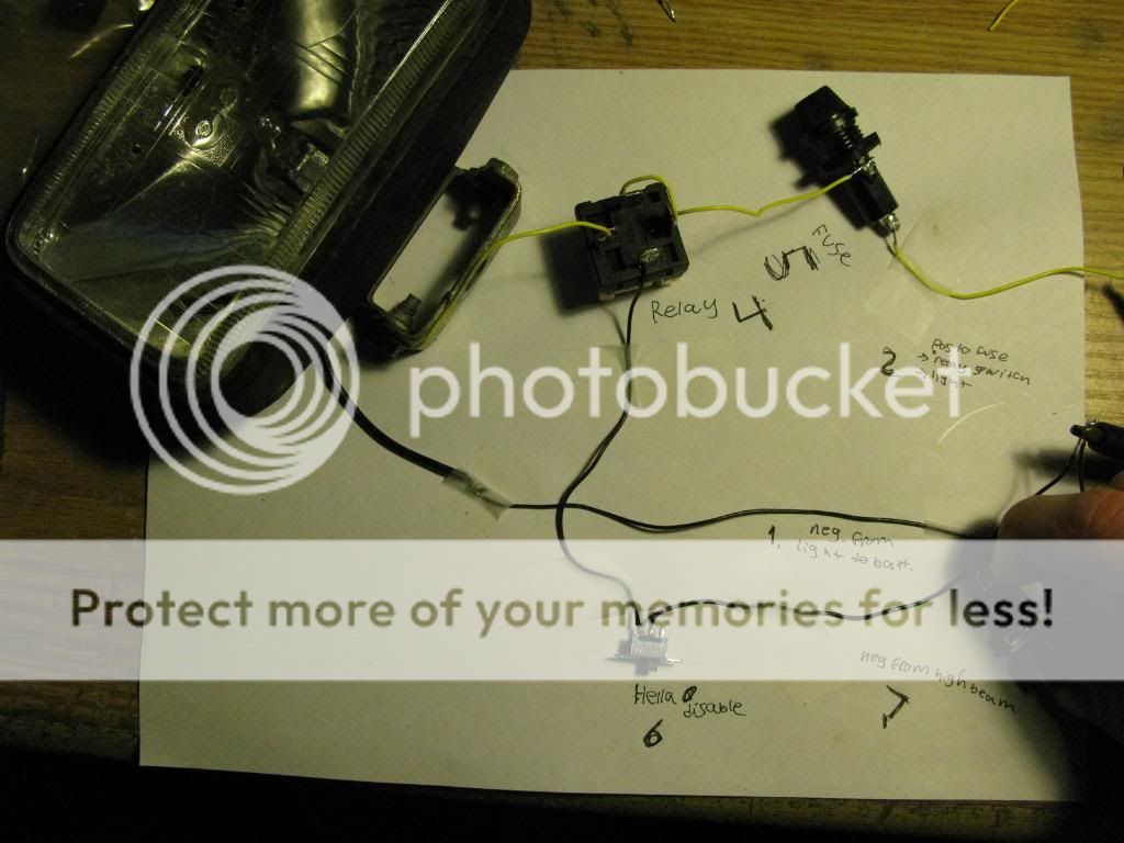
In this pic, high beams are off (no button push), let's flip the switch!
Nothing happens! Good, that's what's supposed to happen.
But now, if we push the high beam button, the hella will come on!
GO ON YOU IDIOT, PUSH THE BUTTON!!!!
Ok...
It works, of course, because Chris wired it.
If you don't understand it now, comment and I'll make you understand it.
DISCLAIMER:
If you mess up the wiring in your car or electrocute yourself, it isn't my fault!!
I have no certification, degree, training, etc working with electricity. I make lots of money wiring boats though, so I know what I'm doing.
HAVE FUN!
Also, I focus on wiring hellas, so read on if that's what you want.
So what the heck IS a relay?
Why would I ever use a relay?
How do I use a relay?
It's pretty simple, folks. A relay is a switch. I'm going to assume here you know how to hook something up to a battery with a switch. That's fairly straight forward, right?
Well, a relay is pretty much just as simple.
A relay is a switch that, instead of being turned on and off by user input (ie. Your finger), it's turned on and off by an electrical signal.
There are a few reasons you would use a relay, but the general idea boils down to this. You want to turn something on and off with a signal load that can't support the full current of what you want to run. WHAT THE HECK DOES THAT MEAN?!
It means this. Say I want to add 4 Hella 500's to my car. I want them to come on when I turn on my high beams. But here's the problem, I can't just wire them into the car wiring harness to my high beam light bulb. It's only designed to handle the pathetic whimpy high beam. So adding ~14 amps to that circuit will hopefully just blow the fuse. I say hopefully blow the fuse because the alternate is it'll melt your wiring and start a fire.
You could run a wire into your cabin to turn the hellas on and off with battery power, but that's annoying. Now you have to turn off your high beams AND hellas for traffic.
SO here is where you meet Mr. Relay. Remember, he's a switch. So you have power directly from your battery to the hellas using the relay as a switch to turn them on and off.
That's great, how does the switch know to turn on and off?
It uses the power to high beams as a SIGNAL to turn the relay switch on, or off. So no power (ok, like 1/4 of an amp) is drawn from the car wiring. Pretty nifty, eh?
Ok dood, that's confusing, give me some pictures!!!
I've disected a relay for you.
Here's a relay in the off state.
Note a few things, the coil. That is what the signal goes to. The coil is an electro-magnet. When it gets power it physically moves the contacts. The things you can see at the front of the realy.
When you give it power the contacts move and connect the circuit.
This is what it looks like on
This is the case of the relay, it has the wiring diagram. The numbers correspond to numbers by the terminals on the bottom. More to follow.
Here's the case.
From this picture, it's easy to figure out how it works.
87 and 30 are the switch terminals. The load terminals, the one the power wire from the battery to the hellas goes through. Think of this half just like a normal person-operated switch.
85 and 86 are the coil. When you give the coil power it's like taking your fat finger and pushing a physical switch. It connects pins 87 and 30 together to make the circuit to turn on your lights.
I should note here, polarity doesn't matter. So you can hook up the coil either way, and have power going through the switch either way.
Here's the bottom of the relay, the part you hook stuff to.
You can see it has the same number that were on the cover.
Note: the switch contacts are copper colour. The signal contacts are silver colour. Almost all the relays I've seen are like this, so that's a big help.
Ok, so I understand what a relay is, tell me how to hook wires up to it!!!!
I've made a mock up of how your car is wired on my desk. So here we go.
In case you can't read my crappy hand writing, this is what the numbers are.
- Negative from light to battery
- Positive from battery to fuse to relay to light
- There isn't one
- Relay
- Fuse
- Hella disable (more on that)
- Negative signal from high beam (I'll explain that)
Also, you'll see I've scribbled some yellow with paint to emphasis there's a yellow wire there. It's hard to see in the pic.
So what do we have here?
Power will flow from the battery to a fuse. That's pretty straight forward. The fuse is protecting both the relay/light circuit, AND the signal wire circuit.
The power goes from the fuse to the switch half of the relay, then to the light. (not a hella in this case, but still 55w)
There's a negative from the light to the battery
So far, this is straight forward.
Then my scribbly yellow to half of the coil. We need positive and negative to power the coil, negative comes from the high beam, so I gave it positive downstream of the fuse. So now the coil has a fused positive. Makes it for a safe installation.
Then the negative to turn on the coil from your high beam. Explained below.
Finally the red button simulates the high beam toggle inside your car, the little tiny switch is the hella disable.
Basically allows you to turn on the high beams but have the hellas off (useful for inspection, etc).
So now you can see, if the high beam button is pushed AND the little switch is on, negative will be delivered to the coil. It'll turn on, close the switch, and turn on the light.
--------------------
Negatively switch headlights.
I'll take an aside here to explain. Headlights on a subaru are negatively switched. Meaning this. The bulb has two filaments, one for high, one for low. That's why there's 3 pins. The common always gets positive, and negative is SWITCHED to either the low beam, or the high beam pin. Hence, negatively switched. This is why we use the negative from the high beam to activate the relay.
If you have a newer car with a high and low bulb separate, the concept is the same. Your projector/low beam is always on, your high beam gets a negative connected when it comes on
---------------------------
So let's press my buttons.
Currently the hella disable is OFF. We shall press the High beam button, what happens?
NOTHING! Good, that's what's supposed to happen. In the car, the high beam would have come on, the hellas would have stayed off.
In this pic, high beams are off (no button push), let's flip the switch!
Nothing happens! Good, that's what's supposed to happen.
But now, if we push the high beam button, the hella will come on!
GO ON YOU IDIOT, PUSH THE BUTTON!!!!
Ok...
It works, of course, because Chris wired it.
If you don't understand it now, comment and I'll make you understand it.
DISCLAIMER:
If you mess up the wiring in your car or electrocute yourself, it isn't my fault!!
I have no certification, degree, training, etc working with electricity. I make lots of money wiring boats though, so I know what I'm doing.
HAVE FUN!
")